Search
environment

Miniaturized Laser Heterodyne Radiometer
This instrument uses a variation of laser heterodyne radiometer (LHR) to measure the concentration of trace gases in the atmosphere by measuring their absorption of sunlight in the infrared. Each absorption signal is mixed with laser light (the local oscillator) at a near-by frequency in a fast photoreceiver. The resulting beat signal is sensitive to changes in absorption, and located at an easier-to-process RF frequency. By separating the signal into a RF filter bank, trace gas concentrations can be found as a function of altitude.
environment

Soil Remediation With Plant-Fungal Combinations
The technology builds on the existing notion that establishment of trees in contaminated soils can be enhanced through the use of ectomycorrhizal (EM) fungi. EM fungi impart resistance to soil extremes such as high temperature, high acidity and heavy metal contamination. This process for soil remediation utilizes specific plant/fungal combinations that are specifically adapted to conditions created by phenolic application to soils, and abilities of ectomycorrhizal fungi to oxidize these compounds. This is done by taking advantage of the ability of native fungi to upregulate enzyme genes in response to changes in host physiological condition and hence enhance natural phenolic oxidation in soils by up to 5-fold. Ectomycorrhizal mediated remediation of phenolic- based contamination through use of specifically adapted ectomycorrhizal fungi and enzymes utilizes the findings that EM fungi in the genera Russula and Piloderma react with positive growth responses to phenolic-based soil contamination. The activities of enzymes that oxidize these compounds increase in activity by 5 fold when the host tree is partially defoliated, which in turn imparts an increase in phenolic oxidation in soils by a similar amount. Defoliation is done by pine needle removal, where 50% of the needles are removed. This process is performed each year on new growth to maintain defoliation.
Manufacturing
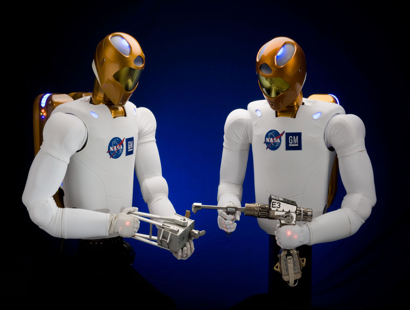
Robonaut 2: Industrial Opportunities
NASA, GM, and Oceaneering approached the development of R2 from a dual use environment for both space and terrestrial application. NASA needed an astronaut assistant able to function in space and GM was looking for a robot that could function in an industrial setting. With this in mind, R2 was made with many capabilities that offer an enormous advantage in industrial environments. For example, the robot has the ability to retool and vary its tasks. Rather than a product moving from station to station on a conveyor with dozens of specialized robots performing unique tasks, R2 can handle several assembly steps at a single station, thereby reducing manufacturing floor space requirements and the need for multiple robots for the same activities. The robot can also be used in scenarios where dangerous chemicals, biological, or even nuclear materials are part of the manufacturing process.
R2 uses stereovision to locate human teammates or tools and a navigation system. The robot was also designed with special torsional springs and position feedback to control fine motor movements in the hands and arms. R2's hands and arms sense weight and pressure and stop when they come in contact with someone or something. These force sensing capabilities make R2 safe to work side-by-side with people on an assembly line, assisting them in ergonomically challenging tasks or working independently.
This NASA Technology is available for your company to license and develop into a commercial product. NASA does not manufacture products for commercial sale.
sensors
Sensing Magnetic Fields
This technology is part of Armstrong's portfolio of fiber optic sensing technologies known as FOSS. The innovation leverages Armstrong's cutting edge work in this area, including its patented FBG interrogation system, which allows for a diverse set of engineering measurements in a single compact system. In addition to magnetic field, other measurements include structural shape and buckling modes, external loads, and cryogenic liquid level. The system and measurement technology is commercially available for research applications. In addition to capitalizing on the significant advancements in fiber optic and laser technologies that have been made to support the telecommunications industry, Armstrong has also partnered with UCLA's Active Materials Lab (AML) to tap their expertise in the field of magnetics.
<b><i>For more information about the full portfolio of FOSS technologies, see DRC-TOPS-37 or visit <a href=https://technology-afrc.ndc.nasa.gov/featurestory/fiber-optic-sensing>https://technology-afrc.ndc.nasa.gov/featurestory/fiber-optic-sensing</a></b></i>
sensors
Streamlined Liquid Level Sensing Using Fiber Optics
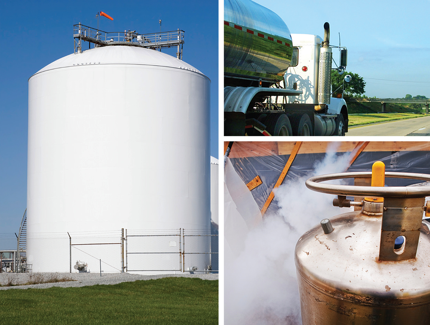
Armstrong has developed a robust fiber optic–based sensing technology that offers extraordinary accuracy in liquid level measurements. The sensing system uses fiber optic Bragg sensors located along a single fiber optic cable. These sensors actively discern between the liquid and gas states along a continuous fiber and can accurately pinpoint the liquid level.
<strong><i>How It Works</strong></i>
The technology uses a resistive heater wire bundled with the optical fiber. The heater is pulsed to induce a local temperature change along the fiber, and the fiber Bragg grating data is used to monitor the subsequent cooling of the fiber. The length of fiber in the liquid cools more rapidly than the portion of the fiber in the gas above the liquid. The measurement system accurately establishes the location of this transition to within 1/4-inch.
<strong><i>Why It Is Better</strong></i>
Armstrong's liquid level sensing technology was originally developed to measure cryogenic liquid levels in rockets, and it represents a significant advancement in the state of the art in this application. Conventional methods for measuring cryogenic liquid levels rely on cryogenic diodes strategically placed along a rod or rack. The diodes are mounted in pre-selected, relatively widely spaced positions along the length of a rod; this configuration provides limited, imprecise data. Furthermore, each diode on the rod has two wires associated with it, which means a single system may require a large number of wires, making installation, connectivity, and instrumentation cumbersome.
Armstrong's novel technology provides liquid measurements with much greater precision, achieving measurements at 1/4-inch intervals. Furthermore, the streamlined system uses just two wires, which greatly simplifies installation and instrumentation. Due to its extraordinary accuracy and ease of use, Armstrong's measurement system offers important advantages for a wide range of applications beyond cryogenic liquids.
<strong><i>In Addition</strong></i>
Researchers have developed a new manufacturing process that improves the ability of fiber optic sensing systems to measure temperature and liquid levels when operating in humid environments. The process involves eliminating moisture from the optical fiber coating, then completing the sensor assembly within humidity-controlled conditions. The resulting sensor hardware provides precise and accurate measurements even when operating in a humid environment.
<b><i>For more information about the full portfolio of FOSS technologies, see DRC-TOPS-37 or visit <a href=https://technology-afrc.ndc.nasa.gov/featurestory/fiber-optic-sensing>https://technology-afrc.ndc.nasa.gov/featurestory/fiber-optic-sensing</a></b></i>
sensors

Fiber Optic Sensing Technologies
The FOSS technology revolutionizes fiber optic sensing by using its innovative algorithms to calculate a range of useful parameters—any and all of which can be monitored simultaneously and in real time. FOSS also couples these cutting-edge algorithms with a high-speed, low-cost processing platform and interrogator to create a single, robust, stand-alone instrumentation system. The system distributes thousands of sensors in a vast network—much like the human body's nervous system—that provides valuable information.
<b><i>How It Works</b></i>
Fiber Bragg grating (FBG) sensors are embedded in an optical fiber at intervals as small as 0.25 inches, which is then attached to or integrated into the structure. An innovative, low-cost, temperature-tuned distributed feedback (DFB) laser with no moving parts interrogates the FBG sensors as they respond to changes in optical wavelength resulting from stress or pressure on the structure, sending the data to a processing system. Unique algorithms correlate optical response to displacement data, calculating the shape and movement of the optical fiber (and, by extension, the structure) in real time, without affecting the structure's intrinsic properties. The system uses these data to calculate additional parameters, displaying parameters such as 2D and 3D shape/position, temperature, liquid level, stiffness, strength, pressure, stress, and operational loads.
<b><i>Why It Is Better</b></i>
FOSS monitors strain, stresses, structural instabilities, temperature distributions, and a plethora of other engineering measurements in real time with a single instrumentation system weighing less than 10 pounds. FOSS can also discern between liquid and gas states in a tank or other container, providing accurate measurements at 0.25-inch intervals. Adaptive spatial resolution features enable faster signal processing and precision measurement only when and where it is needed, saving time and resources. As a result, FOSS lends itself well to long-term bandwidth-limited monitoring of structures that experience few variations but could be vulnerable as anomalies occur (e.g., a bridge stressed by strong wind gusts or an earthquake).
As a single example of the value FOSS can provide, consider oil and gas drilling applications. The FOSS technology could be incorporated into specialized drill heads to sense drill direction as well as temperature and pressure. Because FOSS accurately determines the drill shape, users can position the drill head exactly as needed. Temperature and pressure indicate the health of the drill. This type of strain and temperature monitoring could also be applied to sophisticated industrial bore scope usage in drilling and exploration.
<b><i>For more information about the full portfolio of FOSS technologies, see visit <a href=https://technology-afrc.ndc.nasa.gov/featurestory/fiber-optic-sensing>https://technology-afrc.ndc.nasa.gov/featurestory/fiber-optic-sensing</a></b></i>
mechanical and fluid systems
3D-Printed Injector for Cryogenic Fluid Management
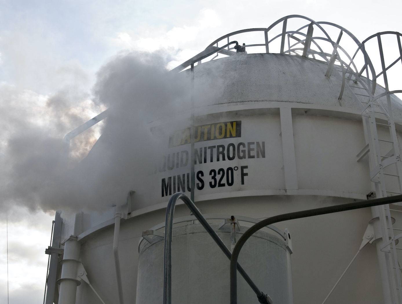
NASA's TVS Augmented Injector includes an internal heat exchanger, a fluid injector spray head, and an external surface condensation heat exchanger - all combined with multiple intertwined flow paths containing liquid, two-phase, and gaseous working fluid. The TVS provides a source of coolant to the injector, which chills the incoming fluid flow. This cooled flow promotes condensation of the tank ullage dropping pressure and maintains incoming fluid flow. The system eliminates the potential for a stalled fill condition and reduces tank pressure during cryogenic fluid transfer. During fill operations, the tank vent can be closed early in the process before fluid is introduced, and, in some cases, the tank vent may not even need to be opened. Furthermore, the TVS Augmented Injector can remove sufficient thermal energy to reach a 100% liquid level in the receiver tank. A cryo-cooler can be used in place the TVS flow circuit for a zero-loss system. The TVS Augmented Injector couples internal fluid flow cooling and external surface ullage gas condensation into a single, compact package that can be mounted to small tank flanges for minimal impact insertion into any vessel. The injector is printed as one part using additive manufacturing, resulting in part count reduction, improved reproducibility, shorter lead times, and reduced cost compared to conventional approaches.
The injector may be of particular interest in applications where cryogenic fluid is expensive, fluid loss through vents is problematic, and/or achieving high filling levels would be helpful. The injector can benefit typical cryogenic fluid transfer between containers or, alternatively, can serve as a tank pressure control device for long-term storage using a fluid recirculation system that pumps fluid through the injector and sprays cooled liquid back into the tank. Additionally, where ISRU processes are employed, the injector can be used to liquefy incoming propellant streams.


